

Water Chiller . Labmit
Introduction
- What is a water chiller?
- Working principles of water chillers
- Types of water chillers
- Design considerations
- And much more…
Chapter 1: What is a Water Chiller?
A water chiller, or chilled water system, is a type of refrigeration system which uses water as a secondary refrigerant. They are used for larger, more complex, heating, ventilating, air conditioning, and refrigeration (HVACR) applications. Typical applications of water chillers are enumerated below.
- District cooling
- Centralized air conditioning
- Hydroponics
- Food and beverage processing
- Pharmaceuticals and medical
- Cold storage
- Thermal Energy Storage (TES) systems
- Machining, waterjet cutting, laser cutting, welding, etc.
- Plastic processing

Opposite of water chillers are direct-expansion (DX) refrigeration systems. A DX refrigeration system directly cools air from the indoor or closed space without the use of a secondary refrigerant. The air passes directly to the evaporator of the refrigeration system. DX types are more suitable for smaller applications such as residential space cooling and small freezers and refrigeration units.
Chapter 2: Working Principle of a Water Chiller
There are two main loops or circuits that make up a water chiller system. These are the refrigeration loop and the chilled water loop. The refrigeration loop is the sub-system that provides cooling. This is where the thermodynamic processes occur. On the other hand, the chilled water loop is a distribution system where cold water is supplied to consumer units. The processes involved in this system are mainly heat transfer.
The Vapor Compression Cycle
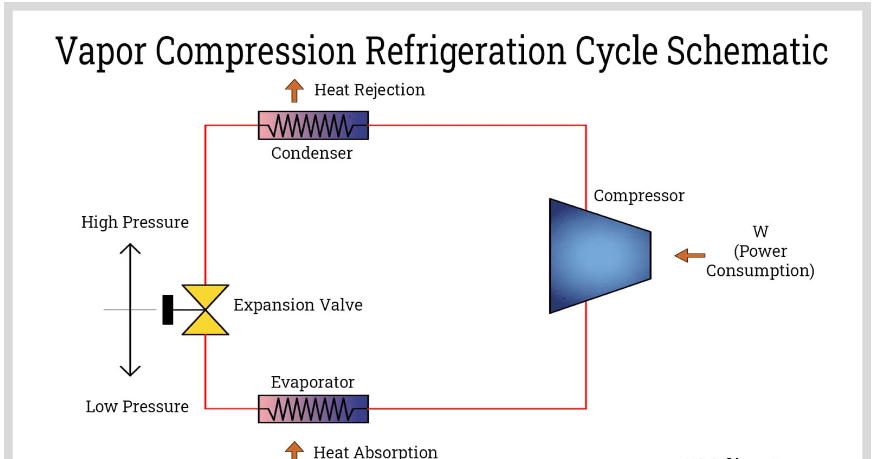
The refrigeration loop works under the principle of a vapor compression refrigeration cycle. In this cycle, the phase of a chemical called a refrigerant is alternately changed from liquid to gas and from gas to liquid using heat exchangers. Aside from changing the phase of the refrigerant, compressors and expansion valves are used to pressurize and depressurize the fluid. The steps of a typical vapor compression cycle are explained in detail below.
Compression
At the beginning of this part of the cycle, the refrigerant is in a low-pressure, vapor phase with the same temperature as the ambient air. It is carrying the heat absorbed from the evaporator.

A compressor pressurizes the vaporized refrigerant which is then discharged to the high-pressure side of the system. At this pressure, the temperature of the refrigerant becomes higher than that of the ambient air or environment.
To increase the pressure of the refrigerant, mechanical energy is expended. Shaft power provided by a motor is used by the compressor to increase the pressure of the vaporized refrigerant. The power input to the system happens during this step.
Condensation
The condenser is the high-pressure side of the refrigeration unit. It is a heat exchanger used to transfer heat from the refrigerant to the environment. Since a thermal gradient exists due to the difference in temperature between the refrigerant and the environment, heat transfer occurs. Both the heat absorbed from the evaporator and the heat generated by the compressor is discharged to the environment.

The environment acts as a heat sink that absorbs the rejected heat of the system. This heat sink can be outdoor air as for air-cooled chillers, or water as for water-cooled chillers.
As the refrigerant is cooled in the condenser unit, it returns to its liquid state. This is because, at this pressure, the saturation temperature of the refrigerant is higher or almost the same as its current temperature. The saturation temperature is the point at which the substance begins to vaporize or liquify if its temperature is further increased or decreased. It is an intrinsic property of the refrigerant.
Expansion
Initially, the liquified refrigerant is in a high-pressure state with the same temperature as the ambient. During the expansion process, the refrigerant lowers its pressure. As the refrigerant becomes depressurized, its corresponding temperature also becomes lower. A small quantity of the refrigerant flashes or turns into vapor which further lowers its temperature. Theoretically, this process happens without heat or energy transfer. After expansion, the refrigerant flows into the low-pressure side of the system.

The expansion process is achieved by passing the refrigerant through an expansion device. Thermal expansion valves and capillary tubes are the typical expansion devices used for vapor compression systems.
Evaporation
The evaporator is the low-pressure side of the system. This is where heat exchange between the refrigerant and the cooling medium occurs. For water chillers, the cooling medium is water or brine.

In the evaporation process, the refrigerant absorbs heat from the water. This elevates the temperature of the refrigerant until it vaporizes. After evaporation, the refrigerant is in a low-pressure state with a temperature the same as the ambient. It then flows to the compressor unit and the cycle repeats.
Water chillers with vapor compression systems are utilized by more than 90% of HVAC applications. The less popular refrigeration cycle is the absorption refrigeration cycle. Consequently, water chillers cooled by an absorption refrigeration cycle are called absorption chillers.

Absorption chillers
are used in industrial areas where a large supply of steam or waste heat is available. In absorption cooling, instead of using a compressor, an assembly of special heat exchangers and other components is used. This process eliminates the large power required by a compressor.The Chilled Water Loop
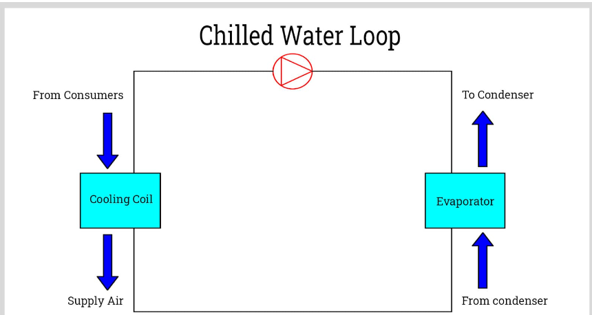
The other heat exchange circuit is the chilled water loop. In this part of the system, water is the main working fluid. Water is the commonly used secondary refrigerant for water chillers. It is extensively used in industrial plants where an abundant supply is required.
For applications requiring much lower temperatures, an antifreeze substance is employed to lower the freezing point of the secondary refrigerant. It prevents ice from forming inside the system. Originally, salt was used as the conventional antifreeze. That is why brine is the popular term used for describing this type of refrigerant. Today, ethylene glycol and propylene glycol are typically used.
Liquid chiller is the specific term for water chillers that use a secondary refrigerant composed of water and antifreeze components.
There are two heat exchangers involved in the chilled water loop: the evaporator and the cooling coil. The evaporator is the same equipment described in the evaporation process of the vapor compression cycle. One side of the evaporator contains the primary refrigerant while the other side has the secondary refrigerant or water.
The cooling coil is the heat exchanger which transfers heat from air or other process fluid to chilled water. Water entering the coil is referred to as the chilled water supply while water leaving is called the chilled water return. For most chiller units, the heat exchange process produces a temperature difference of approximately 8 to 16°F (4 to 9°C). This temperature difference between the chilled water supply and return is called the cooling range. By determining the cooling load and the temperature range, the required chilled water flow rate can be estimated.
Chapter 3: Types of Water Chillers
The previous chapter discussed the two refrigeration cycles used in water chillers, the vapor compression cycle and the absorption cycle. The type of refrigeration cycle employed is one classification of water chillers. Water chillers can also be classified according to their condenser type, compressor, and driver unit.
According to Condenser Type
Water chillers can be air-cooled or water-cooled. They differ in how they reject heat into the environment.
Air-cooled Water Chiller
These types of water chillers have condensers designed to exchange heat from refrigerant to ambient air. They use air as the condensing medium.
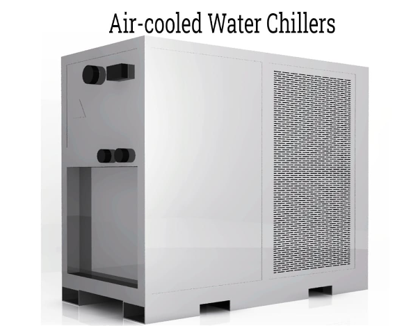
An air-cooled condenser unit typically features finned coils. This increases the surface area of the condenser in contact with air. One or more fans are used to blow air over the finned coil to further improve heat transfer. The amount of heat rejected by an air-cooled condenser depends on the rate of airflow over the coils and the air‘s dry-bulb temperature.
The advantage of using air-cooled water chillers is their simplicity and low cost. They can be installed as stand-alone units without requiring additional infrastructures such as cooling water supply lines and cooling towers.
Water-cooled Water Chiller
As the name suggests, water-cooled water chillers use water as the condensing medium. Since these types of chillers also use water as their cooling medium, two water loops exist in the system.

Water-cooled condensers typically operate with a cooling tower. Cooling towers are heat exchangers, but instead of the usual conduction-convection type of heat exchangers, it generates cooling by bringing water and air into contact. They supply cooling water to the condenser unit which is used to cool the refrigerant.
Water-cooled chillers are used in large industrial plants where a cooling water supply is readily available. Cooling is provided to the condenser at a much higher efficiency compared to air-cooled types.
According to Compressor Type
Water chiller compressors can be centrifugal, screw, scroll, or reciprocating. Each type of compressor has its advantages and disadvantages. Selecting which to use usually depends on the required cooling capacity.
Centrifugal Water Chiller
A centrifugal water chiller has a refrigeration unit that uses a centrifugal-type compressor. A centrifugal compressor increases the pressure of the gas by increasing its kinetic energy. The fluid is then slowed down to convert its kinetic energy to potential energy in the form of static pressure. Their operating principle categorizes them as dynamic-type compressors.

Because of the high capacity of centrifugal compressors, centrifugal chillers are desired in applications with high cooling loads. They also have higher operating efficiencies or coefficient of performance (COP) at peak loads than other types.
Screw Water Chiller
Also known as helical-rotary water chillers, this type of chiller uses a screw compressor to provide mechanical work for its vapor compression cycle. A screw compressor is a type of positive-displacement, rotary compressor which typically uses two helical screws as rotors. Compression is made by trapping the refrigerant in the cavities between the threads of the rotor. The volume of these cavities progressively decreases which then increases the pressure.

Capacity-wise, screw water chillers are used for small to medium applications. Because of their high partial-load efficiency, they are used in applications with varying cooling load demands. Moreover, they do not develop surges when used at low loads, unlike the centrifugal and reciprocating types.
Scroll Water Chiller
The compressor used in scroll water chillers also belongs to the category of positive-displacement, rotary compressors. It has two co-wound spirals or scrolls with one acting as the rotor while the other as a stator. The rotor does not actually rotate but moves eccentrically relative to the other. The refrigerant trapped between the scrolls is transported towards the center where the volume is progressively decreased.

Scroll chillers are typically used in small cooling load applications. To increase its capacity, one or more scroll compressors are used in one chiller package. In terms of efficiency, they have comparable COPs to the screw types. When used in conditions with varying cooling loads, there are a number of refrigerant control methods available such as speed control and variable displacement control.
Reciprocating Water Chiller
This water chiller uses a reciprocating piston or plunger to draw and compress the refrigerant. Because of their nature of producing compression, they are also classified as positive-displacement compressors.
A reciprocating water chiller is now becoming an obsolete chiller technology because of the drawbacks of its compressor. Reciprocating compressors have a noisy operation, poor reliability, and short service life. The only advantage is their affordable cost.
Chapter 4: Design Considerations for Water Chillers
The design of water chiller systems is affected by a variety of factors. For equipment and process units with manufacturer-specified chilled water parameters, the process can be straightforward as the cooling capacity is already known. However, for HVAC applications, the process is more complex since cooling load calculation and air parameters must be established. Moreover, other important aspects of the design must be considered such as controls, configuration, and piping.
Below are some of the characteristics that must be specified when designing water chiller systems.
Cooling Load and Cooling Capacity
Cooling load is the rate at which energy or heat is extracted from a closed space to keep a required temperature and humidity range. It is usually specified in tons of refrigeration (TR or TOR) or in BTU per hour. One TOR is equal to 12,000 BTU/hr or around 3.5 kW.
The cooling load in air-conditioning and ventilating applications is influenced by a variety of factors including solar radiation, conductive and convective heat transfer through the building envelope, infiltration of outdoor air, and internal heat generation from occupants, equipment, lights, and other sources. There are different methods available to calculate the cooling load. Some of these methods are the transfer function method (TFM), cooling load temperature differential (CLTD), heat balance, and time-averaging (TA) method. These can be found on ASHRAE Handbooks and other standards established by international organizations such as ISO and EN.

For refrigeration equipment and process cooling applications, the cooling load is determined based on the requirements of the downstream system. Methods of heat generation vary from each industry. But typically, their heat load calculations are much simpler than air-conditioning and ventilating applications. Equipment cooling specifications are usually provided by the manufacturer along with other design parameters such as chilled water flow rate and temperature.
After calculating the cooling load, the cooling capacity can be established. Cooling capacity refers to the rate of cooling a chiller unit can provide. They are usually slightly higher than the cooling load.
Chilled Water Supply Temperature and Flow Rate
The process of determining the chilled water temperature and flow rate starts by establishing the cooling coil specifications. In HVAC, the cooling coil exchanges heat between the chilled water and returning air. Air parameters influence the chilled water supply temperature and flow rate. They are evaluated together with the cooling load. Standards recommended by organizations such as ASHRAE and psychrometric calculations are used to determine the required air parameters.
In refrigeration equipment and process cooling, the cooling coils are integrated into the system in the form of cooling jackets and coils. Most of the time, there is no psychrometry involved. Thus, the chilled water supply temperature and flow rate are easily determined using heat exchanger calculations. Other methods are also employed depending on the application.
Cooling Capacity Control
In addition to determining the cooling capacity, the frequency and duration of the peak load must be evaluated. Some applications have changing conditions that most of the time, the chiller unit will operate at partial loads. Therefore, the method of varying cooling capacity must be considered.

Different types of water chillers feature different designs of capacity control. For example, scroll water chillers control their capacity by motor speed control using variable frequency drives (VFD) or inverter, or by variable displacement utilizing solenoids to open or close compression chambers.
Centrifugal and screw water chillers, on the other hand, are controlled by reducing refrigerant flows into the compressor. Inlet guide valves or inlet valves are used to adjust the flow. Capacity control using VFDs is also available for centrifugal compressors.
Multiple Water Chiller Configurations
For large-scale applications, multiple water chillers may be a desirable route than a large, single chiller. Using multiple chillers offers several advantages.
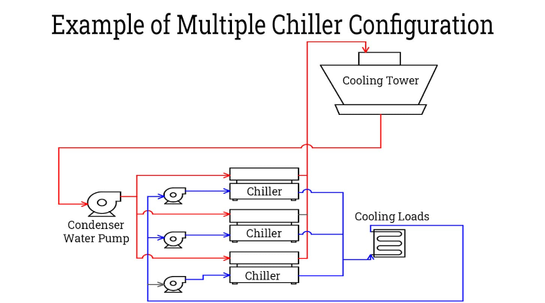
Higher Operating Flexibility. As discussed previously, chillers frequently operate at partial loads. Having two or more chillers in a partially loaded system presents an option to shut down one chiller to decrease capacity. This allows the other chillers to operate at their rated capacities. Thus, the system maintains its optimum efficiency.
Reliability. In a single chiller configuration, if the unit breaks down, the whole cooling system will be as well. No cooling will be available for the entire facility. For multiple chiller systems, some cooling capacity is still available without shutting down the whole system. Also, downtime can be eliminated by installing a spare chiller.
Compressor Driver
The compressor driver is the component that provides mechanical power to the refrigeration unit‘s compressor. There are two types: electric-driven and engine-driven.Electric-driven
These types of chillers are driven by an electric motor to supply shaft power to the refrigeration unit‘s compressor. They are the most common type and seen in every HVAC application. Electric-driven water chillers can be divided into three types according to their construction.
Open-type Chillers:
A chiller classified as open-type has a separated motor and compressor. Their shaft is connected by a coupling. Its main advantage is repairability. The motor can be easily accessed without the need for additional dismantling processes. Moreover, the motor does not contaminate the refrigerant in the event of failure.

The downside of open-types is the risk of refrigerant leakage. Shaft seals are required to prevent the refrigerant from leaking which adds complication to the assembly. Open-type compressors are normally used for large industrial chillers.
Hermetic Chillers:
In this type, the motor and compressor are assembled together inside a closed shell. The shell is permanently sealed by welding. The motor is cooled by the refrigerant flowing into the compressor.
Hermetic sealing solves the problem of refrigerant leakage. However, once the motor fails, it can contaminate the refrigerant. Also, its repair is much more difficult. This makes them limited to small to medium-scale applications.

Semi-hermetic Water Chillers:
Semi-hermetic water chillers are the same as hermetic types except for the construction of the compressor shell. Instead of permanently welding, the shell is bolted allowing for limited serviceability.
Engine-driven Water Chillers
Engine-driven water chillers employ gas or diesel engines to run the compressor instead of the usual electric motors. They are commonly used as stand-by units for additional reliability. In the event of power failure, engine-driven water chillers kick-in providing cooling to critical processes and equipment.
Aside from being independent of the plant‘s power supply, engine-driven chillers can also operate at varying speeds, unlike ordinary electric motors which have a fixed speed. Variable speed for electric drives can only be attained using VFD motors which are more expensive.
Pump and Piping
Another important design consideration for chilled water systems is their pump and piping system. The pump and piping system distributes chilled water to consumers and processes equipment. For new installations, this must be designed properly to maintain the right water flow rate, and in turn, the right cooling capacity.

The usual design process involves calculating the pump brake horsepower. The pump brake horsepower is given by the chilled water flow rate and the total pump head. Estimating the chilled water flow rate was previously described in this section. The total pump head, on the other hand, is computed by calculating any increase in elevation and the frictional losses in the piping.
Another factor to consider is the type of piping material. Water can have impurities such as salts and microscopic organisms which can scale, foul, and accelerate corrosion of all wetted parts. The right piping material must be considered to prevent any issues on equipment reliability while meeting a reasonable cost. Typical distribution piping materials used are carbon steel, copper, and PVC. For the internal piping of chiller units, stainless steel and copper are used.
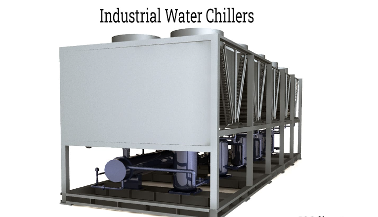
Chapter 5: Industrial Water Chillers
Industrial water chillers are an essential part of manufacturing operations for providing the required temperatures for production processes. They have been adopted for a variety of industrial applications where low temperatures must be met and held for extended periods of time and for accurate performance of equipment. Industrial water chillers are dynamic forms of water cooling equipment that remove heat and guarantee constant temperature, pressure, and air current for a refrigeration system.
The various types of industrial water chillers work by circulating cooling fluid to equipment that require cooling for the completion of a production process. The use of industrial water chillers is due to the types of cooling applications that are necessary for production facilities that cannot be met by a system of fans due to the large scale nature of industrial applications. The exceptional efficiency of industrial water chillers has made them the preferred cooling system and the reason they have been chosen to meet the specific needs of a production operation or scenario.

How Industrial Water Chillers Work
Processes of industrial production generate a great deal of heat from friction, equipment, heating components, ovens, burning, and heat treatments. For the protection of workers and equipment and the safety of the work environment, industrial chillers direct heat away from equipment, workers, and finished products. Their systems are far different from those designed for a HVAC system. A system of pumps in the system directs cooled fluid from the chiller to one or several processes in order to remove heat. The extracted warm liquid is circulated back to the chiller where the heat is expelled, and the fluid is chilled for another cycle.

Parts of an Industrial Chiller
The parts of an industrial chiller are like those of smaller chillers but are more robust and dynamic to meet the challenges of cooling large pieces of equipment while being constantly in operation. As with other forms of chillers, the condensers of industrial chillers are classified as air cooled or water cooled.
- Evaporator - In the evaporator of an industrial water chiller, heat boils the refrigerant and changes it from a liquid to a gas to be sent on to the compressor. The key to the process is the pressure under which the vapor leaves the evaporator.
- Compressor - The most common type of compressor for industrial chillers are
scroll compressors, which work by compressing the refrigerant between spiral plates with one plate being stationary while the other one orbits. As the orbit plate swirls, the trapped gas is forced into a small space and exits through the compressor’s center outlet. Large industrial chillers may have multiple scroll compressors for a single industrial water chiller for redundancy, efficiency, and the handling of heavy loads.
- Condenser - The condenser of an industrial chiller is responsible for removing heat from the high pressure and high temperature refrigerant vapor by functioning like a heat exchanger. It efficiently makes the phase transition of the refrigerant from a vapor to a liquid, which makes it possible for the refrigerant to fit into the water chiller cycle.
- Expansion Valve - The liquid refrigerant moves from the condenser to expansion valves where the pressure of the refrigerant is reduced before being sprayed into the evaporator. The pressure drop cools the refrigerant. When the capacity of the evaporator increases, the expansion valve releases more refrigerant into the evaporator. As the capacity decreases, the expansion valve releases less refrigerant. Additionally, the expansion valve maintains the pressure difference between the condenser, which is at high pressure, and the evaporator that is at low pressure.
Industrial water chillers play a significant role in industrial processes by maintaining tight and precise temperature controls and cost effective engineering solutions. They have the ability to support 100 or more pieces of equipment and are able to be adjusted for expansion and industry growth.
The friction, stress, and continuous operation of industrial mechanisms and tools make it essential to have a reliable cooling system that can withstand the rigors of the many processes and be able to function in those conditions without failure. The designers and manufacturers of industrial chillers are aware of the harsh conditions that industrial equipment must endure and engineer their chillers to meet and exceed the environments, conditions, and challenges of product production.
How to Choose an Industrial Water Chiller
All the positive attributes of industrial water chillers may make it seem an easy to purchase water chiller. Regardless of their function, industrial water chillers are high capacity pieces of industrial equipment that require careful consideration during the purchasing process. An essential aspect of the selection process is to choose the right chiller to fit the needs of an application or a wide range of applications.
Water chiller manufacturers work with their clients to design, engineer, and build a chiller that exactly meets the requirements of a client’s industry and temperature requirements. During the initial phase of the process, experts from water chiller manufacturers meet with clients and visit their facilities to examine the working conditions and determine necessary temperature levels. As a part of relationship selling, producers work with their clients to ensure the proper fit of a chiller to the conditions.
In the initial phases of the selection process, manufacturers work to select a water chilling system that meets the needs of the environment and the budget of the client. It is this partnership that guarantees the right chiller for the situation. Additionally, it may be necessary to engineer a unique configuration for special temperatures and environments, activities that every manufacturer provides without hesitation. An assurance from water chiller manufacturers is that their equipment adheres to the strict standards of the Environmental Protection Agency (EPA).
Other Factors Related to Water Chiller Selection
- Cooling Fluid - The fluid for an industrial water chiller is chosen for its performance and equipment compatibility. The performance of a fluid is determined by its properties at a given temperature, such as its heat, viscosity, and freezing and boiling points.
- Fluid Temperature - A water chiller’s cooling capacity is affected by its setpoint temperature. Lower temperatures increase the load on the system while higher temperatures decrease the load.
- Pressure and Flow Requirements - As can be seen by the description of a water chillers operation, pressure plays a large part of a systems operation. In order for a system to perform properly, it must have a pump that meets the needs of the system. Additionally, the flow rate, in conjunction with the pressure, is a major factor in the process of heat transfer.
- Chiller Size - Selecting the correct size of a chiller for a process is the function of the chiller manufacturer, who has all of the necessary data and expertise required to match the right chiller with a process, operation, or function.
Conclusion
- A water chiller, or chilled water system, is a cooling system that uses water as a secondary refrigerant. They are used for large, complex heating, ventilating, air conditioning, and refrigeration (HVACR) applications.
- The main loops or circuits of a water chiller are the refrigeration loop and the chilled water loop. The refrigeration loop is a subsystem that provides cooling, while the chilled water loop is the distribution system where cold water is supplied to consumer units.
- Water chillers can be air-cooled or water-cooled, which differ in how they release heat into the environment.
- Water chiller compressors can be centrifugal, screw, scroll, or reciprocating. The selection of a compressor depends on the load of the system and the required cooling capacity.
- Processes of industrial production generate a great deal of heat from friction, equipment, heating components, ovens, burning, and heat treatments. For the protection of workers and equipment and the safety of the work environment, industrial chillers direct heat away from equipment, workers, and finished products.
collector
Emran Mia
Fabrication Engineer
LABMIT


Post a Comment